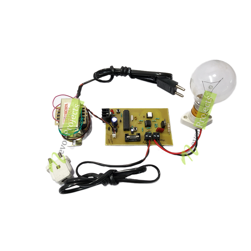

The automatic change over and mixer circuit in manual operation of generator field gain voltage regulation, and when the automatic manual change over and mixer circuits operate manually, the AVR (automatic voltage regulator) cannot operate. This circuit is arranged in an auto-manual connection switch and a circuit to control the voltage amplifying the generator. This will be removed by installing VR (variable resistance) on set voltage and sensing voltage.Īutomatic manual change over and mixer circuit The voltage difference is called an error voltage.

The amount of sensing voltage with set voltage does not have the same value so that the difference in the voltage range. The comparative amplifier circuit is used as a comparison between sensing circuits and set voltage. The advantage of the sensing circuit is to have a rapid response to the generator output voltage. The three-phase generator voltage is supplied to the sensing circuit passing PT and 90R first, and the three-phase output voltage of 90R is lowered then transmitted by diode circuit, and leveled by capacitor circuit and resistor and this voltage can be adjusted with VR (Variable Resistant). Thus, if there is a change in voltage the output of the generator will be stabilized by the AVR automatically because it is equipped with equipment such as a device used for limiting minimum amplifier or maximum that works automatically. And also vice versa if the output voltage of the generator exceeds the nominal voltage of the generator, the AVR will reduce the strengthening current in the exciter. If the generator output voltage is below the nominal voltage of the generator, the AVR will increase the amplification of the exciter. The working principle of the AVR is to regulate the strengthening current in the exciter. The operating system of the AVR Unit (Automatic Voltage Regulator) functions to keep the generator voltage constant in other words the generator will still issue a voltage that is always stable not affected by changes in load that are always changing, because the load greatly affects the generator output voltage. A simple model of an AVR on a generator whose amplification system uses a shunt type DC generator is displayed as shown below:ĪVR on the generator serves to regulate, control and monitor the voltage that comes out of the main stator based on the principle of feedback. AVR working Model:Īn AVR works by involving several parts of a generator. When the generator is too amplified, it must provide a lagging current to the system because the lagging current will produce an anchor flux that will counteract the rotor flux to reduce reinforcement that is too large. The condition of overexcitation is a condition of the generator whose gain is too large (too amplified) so that it will supply a lagging current to the system. When the generator is less amplified, it must provide an overdue current to the system because the overdue current will produce an anchor flux that will strengthen the rotor flux. This can be reviewed according to the GGM / flux of the anchor reaction. Under excitation condition is a condition of the generator whose gain is less (less reinforced) so that it will supply the current to the system. There are two conditions occurred in regulating the voltage, which is listed below: If the Generator terminal voltage is less than the reference voltage, the AVR increases D.C. The AVR compares the Generator terminal voltage with a preset reference voltage. The Generator terminal voltage is fed to the AVR which compares it with a reference value and an error signal is generated. Automatic Voltage Regulator (AVR) is an automatic control device that is used to keep the terminal generator voltage constant.


 0 kommentar(er)
